User Guide
Getting Started
The first step is to connect cameras to GigE or GigE Vision network adapters.
Install Pylon software. For non GigE Vision adapters Pylon will install filter drivers.
Verify or setup IP addresses of the cameras. See Network Setup for more details.
Optionally cameras can be checked with Pylon Viewer.
If several cameras need to share the same adapter, bandwidth load must be estimated. See Bandwidth Control for more details.
Note
For really high-performance note that the performance intermediate routers and hubs can affect the system operation
Network Setup
Basler GigE cameras can run on 100Mbit and 1000Mbit adapters. If high performance is expected, the camera can to be connected directly to dedicated GigE or GigE Vision adapter on the target PC.
Note
Running on 100Mbit requires tight bandwidth control
For non GigE Vision adapters Pylon will install filter driver. This can be verified by going to Control Panel-Network Connections-Connection Properties. Make sure filter driver is present and activated on the correct adapter. Cameras won’t work without filter driver.
When Basler cameras are connected they do get IP addresses. Even so, pylon IP Configurator should be invoked to verify that cameras get correct addresses.
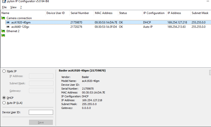
Begin by verifying that adapters have correct subnets. Then see that cameras have IP addresses from those subnets. Use static addresses if automatic or dhcp does not work.
Pylon Viewer
pylon Viewer from Basler allows to view existing connected cameras, open them, change their parameters and test different modes of operation.
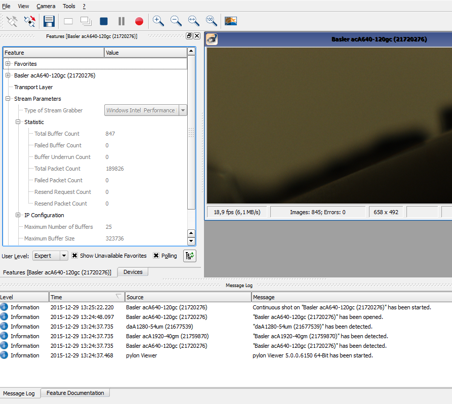
Among other things pylon Viewer can be used to stress test network setup. Open and run cameras at high framerates and monitor message log for error messages. Also notice read-only counters at Stream Parameters-Statistics. See if failed frame count stays at zero.
Bandwidth Control
Although theoretical throughput of Gigabit network is around 120MB/s, it should be expected that cameras can transfer maximum of 80-100MB/s of image data.
- Multiple cameras will share the available bandwidth
- More bandwidth can be added to a system by using multiple adapters
- Adapter performance can be improved by enabling Jumbo Frames and disabling Interrupt Moderation
- Limiting camera framerate is an easy way to do bandwidth management. See Triggering Control for more details.
For standard GigE adapters jumbo frames (or large packets) can be enabled. This will increase the capacity of the system. Go to adapter properties and click on Configure, then go to Advanced tab and search for jumbo frames. Not all adapters and routers support jumbo frames.
At the same time Packet Size in camera driver must be adjusted to match size of jumbo frames (see transport layer parameters)
However it would work best only on short direct connections. Over longer distances large packets can make things worse.
GigE vision adapters will be already optimized for this, no additional setup needed.
When there are several cameras on the same adapter, the sum of load across all cameras must not exceed total line throughput. However, even then there may be packet conflicts - if cameras grab images simultaneously and try to transfer them as quickly as possible.
The following parameters may be adjusted to avoid packet conflicts (more details in transport layer parameters):
- Packet Size - making it larger (as allowed by network adapter) will reduce load. But conflicts on larger packets will take longer to resend.
- Inter-Packet Delay - may be increased to reduce load.
- Frame Transmission Delay - may be differentiated across several cameras.
- Bandwidth Reserve - reserve bandwidth to handle packet resend and transmission collisions
- Bandwidth Assigned - read-only parameter tells exactly how much bandwidth a camera is using. Have a sum of this for all cameras on the same adapter.
Note
- In a system were you do not need maximum performance setting the Bandwith Reserve to a value between 10 to 30% will handle improve the robustness and can be recommended.
- The number of collision may increase having multiple hw triggered cameras.
Triggering Control
By default camera will be in freerun mode without framerate limit. Scorpion may trigger images at defined slower rate, but camera would still stream images as fast as possible under given image size, exposure, etc. Network may get unnecessarily overloaded.
Note
The framerate is explicitly specified by:
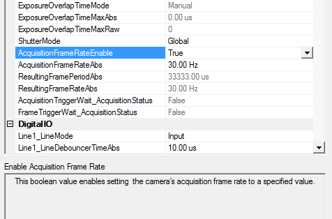
- Enable Acquisition Frame Rate - Enables framerate control.
- Acquisition Frame Rate - Defines max number of images to deliver in one second.
Another option to limit network overload is to use Hardware or Software camera trigger. Trigger is enabled with TriggerMode parameter set to on, then Trigger Source can define either Hardware Line or Software trigger.
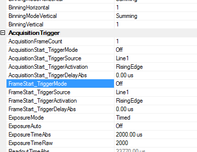
Some Basler cameras provide both AcquisitionStart and FrameStart trigger groups.
Note
They both relate to triggering parameters, but it was observed that if both groups are present, then AcquisitionStart group is ignored by camera.
Therefore either both groups or only FrameStart should be set.
Using Software Trigger
Software Trigger will not be as fast as Hardware trigger but it can be used as an alternative to camera freerun mode, especially when network load must be reduced. In order to use software trigger the following parameters must be checked:
- Trigger Mode is on
- Trigger Source is set to Software
Software trigger will be automatically issued with Scorpion’s Grab command (via python or via Scorpion actions).
Python example: ExecuteCmd('Grab','')
Alternatively software trigger can be issued directly to the camera via setProperty:
Python example: GetCamera("0").setProperty("softwareTrigger", 1)
Scorpion Continous Mode
Scorpion Vision 8 and higher supports continous mode. This mode is implemented in order to reduce the overhead when using high framerates. Scorpion can handle framerates up to 100..250 frames per second. The actual number depends upon camera type and interface used. The continous mode eliminates the need and overhead to issue a Grab command for each image. This means that Scorpion only concentrates to receive the images as fast as they flow into the PC.
Activate continous mode for the first camera:
GetCamera("0").setProperty("continous", 1)
DeActivate continous mode for the first camera:
GetCamera("0").setProperty("continous", 0)
Camera Configuration in Scorpion
Camera parameters can be configured via configuration dialog:
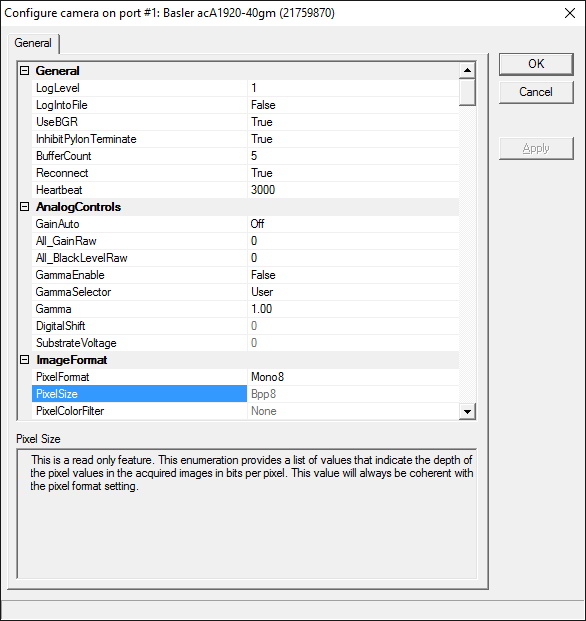
When parameters have been changed press either Apply or OK. In both cases the new parameters (and only those that were actually edited) are written to camera.
But in case of Apply the dialog remains open. The parameter values will be updated and will reflect what actually was accepted by the camera. It may turn out that changing one parameter modifies another (e.g. changing Binning will change Width/Height). This is a convienent way to iteratively navigate through parameter interdependencies towards target settings.
The parameters are provided via GeniCam interface directly from camera. The particular names and order of parameters may differ from camera to camera. However the bulk of essential parameters usually do not change. Below is definition for some of the most common parameters.
General
| Property | Description |
|---|---|
| InhibitPylonTerminate | If enabled then Pylon terminate function will not be called. Enable when using several pylon drivers in the same profile, for example Basler Runner together with Area Scan gige or firewire cameras. |
| Log level | Level 0 suppresses all messages. Level 1 issues error and warning messages. Levels 2,3 issue diagnostic messages. |
| BufferCount | Number of buffers used for grabbing. More buffers will consume more memory. On the other hands buffers will guard against loss of image due to occasional image processing slowdown. Mimumum recommended count of buffers is 2. |
| Reconnect | When set to True camera driver will try to periodically reopen camera in case of network connection loss. |
| Heartbeat | Number of milliseconds between network connection checks. This parameter tells how quickly network loss is detected by camera when there is one. Setting to too low value will add to network congestion. |
ImageFormat
| Property | Description |
|---|---|
| UseBGR | This should be enabled for color cameras, otherwise blue and red will be swapped in the final image. |
| TestImageSelector | This enumeration provides a list of the available test images. Selecting a test image from the list will enable the test image. |
AnalogControls
| Property | Description |
|---|---|
| GainAuto | The gain auto function automatically adjusts the Auto Gain Raw parameter value within set limits, until a target average gray value for the pixel data from Auto Function AOI1 is reached. |
| All_GainRaw | Sets the ‘raw’ value of the selected gain control. The ‘raw’ value is an integer value that sets the selected gain control in units specific to the camera. |
| All_BlackLevelRaw | This value sets the black level control. |
| GammaEnable | Enables the gamma correction. |
| Gamma | This feature is used to perform gamma correction of pixel intensity. |
AOI
| Property | Description |
|---|---|
| Width | Set the width of the area of interest in pixels. |
| Height | This value sets the height of the area of interest in pixels. |
| OffsetX | This value sets the X offset (left offset) for the area of interest in pixels, i.e., the distance in pixels between the left side of the sensor and the left side of the image area. |
| OffsetY | This value sets the Y offset (top offset) for the area of interest, i.e., the distance in pixels between the top of the sensor and the top of the image area. |
| BinningVertical | Sets the number of binned adjacent vertical pixels. Their charges will be summed and reported out of the camera as a single pixel. |
| BinningHorizontal | Sets the number of binned adjacent horizontal pixels. Their charges will be summed and reported out of the camera as a single pixel. |
AcquisitionTrigger
| Property | Description |
|---|---|
| TriggerMode | This enumeration sets the trigger mode for the selected trigger. |
| TriggerSource | This enumeration sets the signal source for the selected trigger. |
| TriggerActivation | This enumeration sets the signal transition needed to activate the selected trigger. |
| ExposureAuto | The exposure auto function automatically adjusts the Auto Exposure Time Abs parameter value within set limits, until a target average gray value for the pixel data of the related Auto Function AOI is reached. |
| ExposureTimeRaw | This value sets an integer that will be used as a multiplier for the exposure timebase. The actual exposure time equals the current exposure time raw setting times the current exposure time base abs setting. |
| ExposureTimeAbs | This float value sets the camera’s exposure time in microseconds. |
| ExposureTimeBaseAbs | This float value sets the time base (in microseconds) that is used when the exposure time is set with the ‘raw’ setting. |
| AcquisitionFrameRateEnable | This boolean value enables setting the camera’s acquisition frame rate to a specified value. |
DigitalIO
| Property | Description |
|---|---|
| LineX_LineMode | This feature controls whether the physical Line is used to Input or Output a signal. When a Line supports input and output mode, the default state is Input to avoid possible electrical contention. Line Mode can take any of the following values: input- the selected physical line is used to input an electrical signal; output- the selected physical line is used to output an electrical signal. |
| LineX_LineDebouncerTimeRaw | Sets the raw value of the selected line debouncer time. |
| LineX_LineFormat | This feature controls the current electrical format of the selected physical input or output Line. Line Format can take any of the following values:
|
| OutX_LineInverter | This boolean value enables the inverter function for the selected line. |
| OutX_LineStatus | This boolean value indicates the current logical state for the selected line at the time of polling. |
| OutX_LineSource | This enumeration selects the internally generated camera signal (source signal) for the selected line. |
| OutX_UserOutputValue | This boolean value sets the state of the selected user settable output signal. |
Note: ‘X’ in property name must be substituted with the line number (0,1,2), e.g. Line1_LineMode.
TimerControls
| Property | Description |
|---|---|
| TimerDurationTimebaseAbs | This float value sets the time base (in microseconds) that is used when a timer duration is set with the ‘raw’ setting. |
| TimerDelayTimebaseAbs | This float value sets the time base (in microseconds) that is used when a timer delay is set with the ‘raw’ setting. |
| TimerX_TimerDelayRaw | This value sets an integer that will be used as a multiplier for the timer delay timebase. The actual delay time equals the current timer delay raw setting times the current timer delay time base abs setting. |
| TimerX_TimerDurationRaw | This value sets an integer that will be used as a multiplier for the timer duration timebase. The actual duration time equals the current timer duration raw setting times the current timer duration time base abs setting. |
| TimerX_TimerTriggerSource | This enumeration sets the internal camera signal used to trigger the selected timer. |
AutoFunctions
| Property | Description |
|---|---|
| AutoTargetValue | The target average gray value may range from nearly black to nearly white. Note that this range of gray values applies to 8 bit and to 16 bit (12 bit effective) output modes. Accordingly, also for 16 bit output modes, black is represented by 0 and white by 255. |
| AutoGainRawLowerLimit | Lower limit of the Auto Gain (Raw) parameter |
| AutoGainRawUpperLimit | Upper limit of the Auto Gain (Raw) parameter |
TransportLayer
| Property | Description |
|---|---|
| GevHeartbeatTimeout | This value sets the heartbeat timeout in milliseconds. |
| Packet Size | StreamChannel0_GevSCPSPacketSize. If using other packet size than default (1500), unless you have already set the packet size for your network adapter during the installation of the Pylon AreaScan software, check the documentation for your adapter to determine the maximum packet size (sometimes called “frame” size) that the adapter can handle. Many adapters can handle what is known as “jumbo packets” or “jumbo frames”. These are packets with a maximum size of 16 kB. Once you have determined the maximum size packets the adapter can handle, make sure that the adapter is set to use the maximum packet size. |
| Packet Delay | StreamChannel0_GevSCPD. Sets delay in ticks between packets sent by the camera. Applies to the selected stream channel. Increasing the inter-packet delay will decrease the camera’s effective data transmission rate and will thus decrease the network bandwidth used by the camera. In the current camera implementation, one tick=8ns. |
| Frame Transmission Delay | StreamChannel0_GevSCFTD. Sets a delay in ticks (one tick = 8 ns) between when a camera would normally begin transmitting an acquired frame and when it actually begins transmission. This parameter should be set to zero in most normal situations. If you have many cameras in your network and you will be simultaneously triggering image acquisition on all of them, you may find that your network switch or network adapter is overwhelmed if all of the cameras simultaneously begin to transmit frame data at once. The frame transmission delay parameter can be used to stagger the start of frame data transmission from each camera. |
| Bandwidth Reserve % | StreamChannel0_GevSCBWR. Used to reserve a portion of the assigned bandwidth for packet resends and for the transmission of control data between the camera and the host PC. The setting is expressed as a percentage of the Bandwidth Assigned parameter. For example, if the Bandwidth Assigned parameter indicates that 30 MByte/s have been assigned to the camera and the Bandwidth Reserve parameter is set to 5%, then the bandwidth reserve will be 1.5 MByte/s. |
| Bandwidth Reserve Accumulator (RO) | StreamChannel0_GevSCBWRA. A software device called the bandwidth reserve accumulator is designed to handle unusual situations such as a sudden EMI burst that interrupts a frame transmission. If this happens, a larger than normal number of packet resends may be needed to properly transmit a complete frame. The accumulator is basically an extra pool of resends that the camera can use in unusual situations. |
| Actual Bandwidth (RO) | StreamChannel0_GevSCBWA. Indicates the bandwidth in bytes per second that will be used by the camera to transmit frame and chunk feature data and to handle resends and control data transmissions. The value of this parameter is a result of the packet size and the inter-packet delay parameter settings. Note: Sum of bandwidth for all cameras on the same NIC must not exceed 125MB/s on a gigabit network. Otherwise frame overruns may occur. |
| Actual Bandwidth (RO) | StreamChannel0_GevSCDCT. Indicates the actual bandwidth (in bytes per second) that the camera will use to transmit the image data and chunk data (if any) in each frame given the current frame size, chunk feature settings, and the pixel format setting. |
| Frame Max Jitter (RO) | StreamChannel0_GevSCFJM. If the Bandwidth Reserve Accumulation parameter is set to a high value, the camera can experience a large burst of data resends during transmission of a frame. This burst of resends will delay the start of transmission of the next acquired frame. The Frame Max Jitter parameter indicates the maximum time in ticks (one tick = 8 ns) that the next frame transmission could be delayed due to a burst of resends. |